800 Watts Out with 28 watts drive on 20 Meters! |
Shown below is a single band RF Linear Amp for 20 meters.The unit was constructed in 2001 and was first placed on the air on 9/11/2001. The tube was a pull from a commercial radio station and the circuit used was from June 88 QST. The QST article had many errors and after many emails with the original author the amp is working properly. I had a problem locating a 3 minute time delay relay and so used some new technology to solve the problem. A PIC16F84 was used to set the three minute delay. |
The circuit is a Pi L and the plate supply is 2000 VDC at 800 Ma. The control circuit features a grid trip circuit and a 40 second delay on the blower fan after shutdown.. The amp was built into a housing that originally had a pair of 813's that was used on 20 meters. Things I would have done differently include remoting the blower. The box is small and the blower makes a lot of noise.I also would have found some alternative to the 2 deck Radioswitch type 86 so it could be band switched. I am contemplating a rebuild to 40 or 80 meters. |
|||||
| Click on the photo description for a larger picture. | |||||||
|
|
|
|
|||||
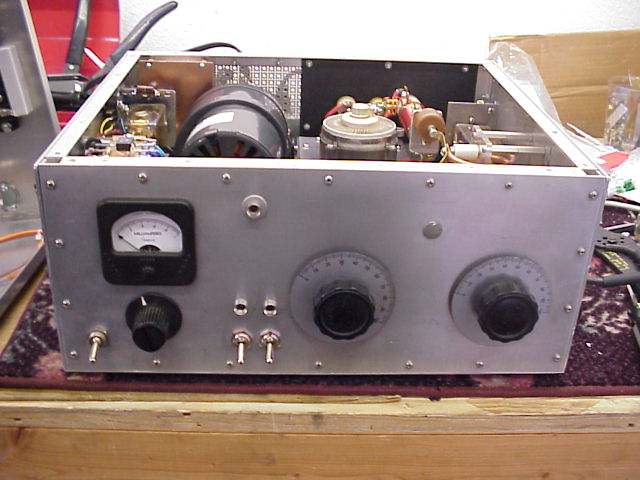
These are shots of a homebrew single 3CX800A7 RF Linear Amplifier. It is a single band unit for 20 meters and the power output is about 800 Watts with 28 watts of drive. The output circuit is a Pi L with a tuned input. The plate supply is 2000 VDC at 0.75 Amp.When a suitable 3 Minute Time Delay Relay couldn't be located, a PIC Microcontroller Circuit was developed as a substitute to provide a precise 3 Minute Time Delay before application of the High Voltage. This amp was put into service on 9/11/2001. |
||
|---|---|---|