A Process for Installing Service Bulletin #8 in the KWM-2/2A.
By Pete Juliano, N6QW After five years of owning my WE Collins KWM-2, I figured it was finally the time to address the installation of Service Bulletin #8. This particular modification has three goals the first of which is to eliminate the AGC (Automatic Gain Control) overshoot, the second to change the source of AGC Bias and the third is to provide a Hang Action (delay) to the RF Amplifier. Combined these three provide a dramatic improvement to the received signals. The parts of the circuit affected by the Service Bulletin are the 1st and 2nd IF Amplifiers V1B and V3B, both 6AZ8’s, and V7 the 6DC6 which is used as the RF Amplifier on both Transmit and Receive. In the case of V7 the AGC control voltage (noted as AVC on the schematic for Automatic Volume Control) is routed through Relay K4 which alternately supplies AGC voltage on Receive and ALC (Automatic Level Control) voltage on Transmit. I think my lengthy delay in doing SB #8 was the mere thought of messing with the work of the Radio Gods (Collins Engineers). Imagine taking a soldering iron to a Collins KWM-2? What if I screw this up? What if the result is worse than the problem? Then there is the practical matter of doing the work on a radio chock full of parts. Fear not as the SB can be installed by those with average technical skills and moderate radio knowledge. Over the years I have developed a process for renovating and repairing radios. I would like to share that with the Collins Community so that perhaps it may remove or mitigate the concerns about repairing or renovating their treasured Collins radios. In retrospect most of the effort on this project does not involve the use of the soldering iron but in planning the project! Spending a good deal of time reading and re-reading the Service Bulletin is time well spent. The SB’s are written so that every step is detailed and there are many notes and advisories. If you do not have a copy of the SB #8, it can be downloaded from the CCA Website Collins identifies all of the parts required for each step. After carefully copying down all of the parts required I then placed an order with my favorite distributor. Trust me, bypass your junk box and buy everything new! The new parts cost for SB #8 is less than $20. The reason I am saying this is that once you install some of the parts, replacement is no simple task. Starting with fresh parts brings you way up on the curve. All of the new resistors were 5% carbon composition ½ watt and the capacitors were the best tolerance I could find. Check the voltage ratings on the capacitors! The parts list contained in the KWM-2 Manual lists all the voltage ratings of the Capacitors. I used disk ceramic capacitors for the 0.01’s and Orange Drops for the others. Polycaps have been suggested for the non-ceramic disks and these are OK too. Order some Teflon tubing and use it liberally as the components are in close quarters so you do not want any shorts. Collins used the best parts and so should you! My next step was to create a hand sketch of the “as built” condition of the components that are impacted in SB #8. Subsequently I created another hand sketch of where the new components are connected in the circuit. In this SB it is not just a matter of changing component values but also of removing and not replacing some components while adding several new components. This hand sketch process is invaluable as it gave me a clear understanding of the existing circuitry and how it would be changed. The hand sketch process also enabled me to visualize where the new components would be installed and to get some feel of part clearance and interference with other components. Here is a sample of one of my hand sketches shown in Figure 1. Taking digital photos is another piece of this process and provides a historical track of how things were in the before and after state.
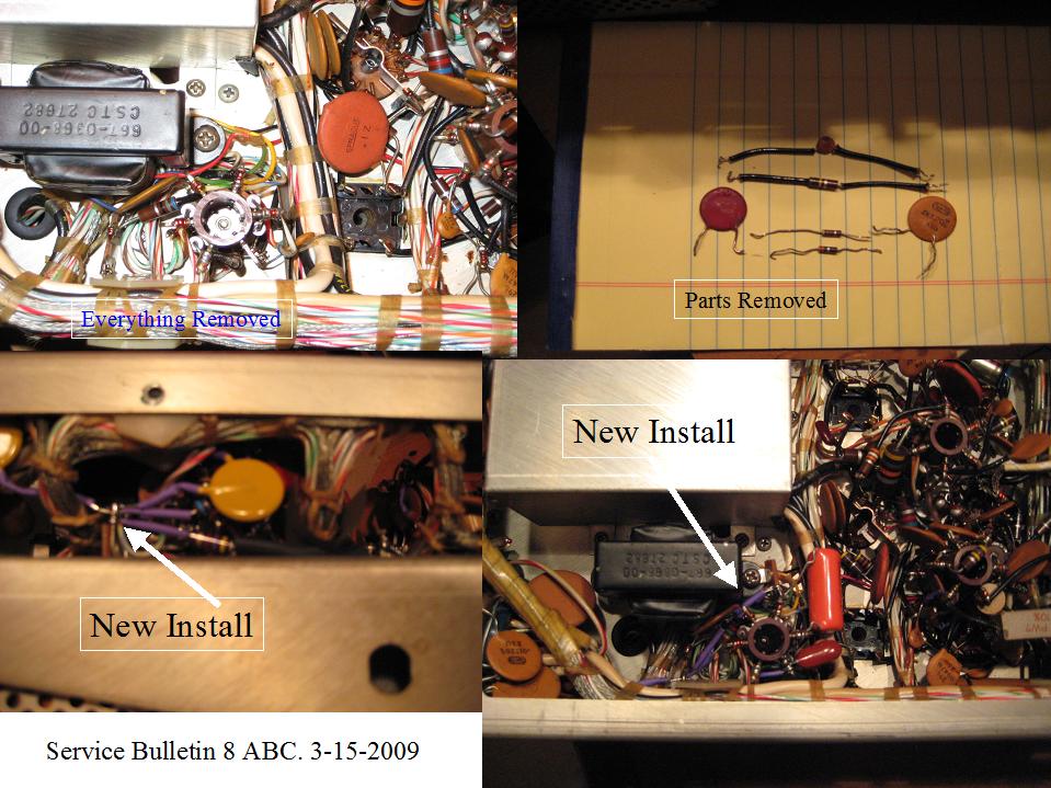
Figure 1. Hand Sketch “As Built” Turret E30, KWM-2 The key to a successful project is a set of good tools and my list includes the following: a small tip temperature controlled soldering iron, forceps, large tweezers, needle nose pliers, flush cut wire cutters, assorted Phillips and straight blade screw drivers, and a small Exacto type knife. Add in a small LED pencil type flashlight, a small pair of cuticle scissors and if you have one a dental pick. Various sizes of Solderwick and or a solder sucker are also on the must list! Careful attention should also be paid to the work area and the lighting. Sufficient space to work on the radio, room for the tools and a place to put the instructions is really critical. Also leave room for you! [A tip from K6XYZ for removing the side brace: apply heat with the soldering iron to the blue gunk on the screws holding the brace in place. It melts the liquid. ] Take another read of the Service Bulletin and make sure you really understand the steps. I do what is called a “dry run”. I took each step and acted as if I actually performed the work so I was fully aware of what needed to be done and had simulated the actual work process. In the case of SB #8, if you will be doing all three parts you are advised not to solder several of the connected parts, as there will be subsequent installations on these connections. For those identified not to solder I did tack solder them so I could test after each section was completed solely for the purposes that I had not disturbed something else in the circuit. Use extreme care with the soldering iron so you do not burn nearby wire bundles or other parts not involved with the modification! We are now ready to start with Part A, which initially involves parts removal and then parts installation. Using the SB, check-off each action, and recheck each step before proceeding to the next step. This is like Heathkit 101 but it is well worth the effort. Starting with the parts removal, accounting for the parts removed to be certain they are the parts designated for removal and finally reinstalling the new parts completes the process. My vintage KWM-2 has the wired in relays and basically Terminal 14 has two connections that carry the AGC Voltage. Before doing Part C, AGC voltage comes from TS8-1 goes to the Terminal 14 and a second wire from terminal 14 goes to E40-I feeding V3B and then onto E60-L to feed V1B. Terminal 13 is the center contact and connects to E70-I and goes to V7. Before Part C, this provides AGC Voltage to all three tubes on Receive. On transmit Terminal 13 connects to Terminal 12, the source of ALC voltage and V7 is now disconnected from the AGC circuit. Part C essentially provides the normal AGC Voltage to V1B and V3B and the Hang-Delay AGC voltage to V7. Taking the connection from TS8-1 and moving it to TS11-1 (new) does part of this. This now connects V7 to the Hang Delay AGC action. But the wire from Terminal 14 to E40-I must now be abandoned and this is Step (h) in part C. A new wire is connected to TS8-1 and to E40-I so that the AGC is provided to V1B and V3B. Was it worth the effort? Yes! The result is dramatic and you are left to wonder how this piece of 1960’s advanced technology ever left the factory without these modifications. I would like to acknowledge input, information and assistance from John Bess, WA5VVT and Dave Harmon, K6XYZ. Figure 2 shown below tells the story in a composite photo of the entire process. The actual SB #8 physical installation took only about an hour but the planning and the “get ready” was over a three-day period. The resulting “perked up” receiver in the KWM-2 is well worth the time spent in planning and executing the Service Bulletin. Figure 2. A photo collage of SB #8 installation on the KWM-2 In summary, the successful installation of Service Bulletin #8 on the KWM-2 /2A is all about knowing and understanding what to do, using quality parts and having the right tools. The pre-planning with the sketches and digital photographs is invaluable to provide a track of where you were and where are you going. Utilizing the technical archives is also important as well as accessing the knowledge base in the Collins Community. Information such as in the Service Bulletins and other documentation/tips contained in the quarterly Signal magazine is a rich resource to keep the Collins radios running for a long time. (Rev 4. 3/26/2009) |