Build Something!
How did this all get started?
HB 17M SSB XCVR using a VXO.
4/13/07 |
Shirt Pocket Sized 1 watt 17M SSB transceiver? Yes, that is a possibility but not with through hole components. Using surface mount SMT that could be a reality.
Special Note about the Drawings. The Drawings were done in Power Point and with the latest Microsoft Browser appear to be missing lines, fuzzy or distorted. When the Drawings are displayed, simply "Left Click" with your mouse and the drawings will appear full size and clear. |
|---|
Block Diagram of the Prototype Transceiver
This prototype is based on work and designs done by Ron Taylor G4GXO and employs a bilateral approach. Ron developed a project called the Belthorn Special and this employs many of the circuits used in that radio. Use of diode steering and DC switching enables this radio to provide strong performance with minimum components. This is a bi-lateral design where circuits are used both on transmit and receive dependent upon diode steering. The very first bi-lateral transceiver employing transistors was the SBE-33. This was a hybrid transistor and tube radio. It had some shortcomings with AGC control and limitations in frequency. But it was advanced technology in the 1960's. See GQRP SPRAT #128 for the IF Amp design detail.
The transceiver was just completed in January 2007. It uses a 4.9152 Mhz IF and a VXO operating at 23.04 Mhz. The VXO uses standard 11.520 Mhz Computer Crystals that are frequency doubled in a diode type doubler. The Frequency range is from 18.120 to 18.150. The power out is 4+ watts. So far seven states have been worked (all in the mid-west) from my QTH near Seattle. I also married up my 100 watt SS amp to the radio and have worked DX in Japan, Mexico, Costa Rica and The Isle of Man (GD6). Not bad for a board that is 4"x6".
Yes it will go in a box but I am having too much fun and am still evaluating various aspects. The matching transformers to the crystal filter were originally FT 37-43. I replaced those with similar transformers using FT 23-43 cores. These work and are much smaller but there is a performance difference with the FT 37-43's. For the shirt pocket radio the smaller cores would work OK. For a 4 pole ladder filter I used 47 PF coupling caps (all five) and assumed an impedance of 150 ohms. That seems to be pretty close.
As with the Belthorn NE5534's are used for the Mic and Audio Pre-Amp stages and the output is the venerable LM386. This current version does not have an AGC circuit but that can be added.
The bandpass filter was designed using W7ZOI's tables in the back of the Solid State Design Manual. I assumed a very narrow bandwidth of 18.0 Mhz to 18.268 Mhz. It is pretty much a by the numbers approach. I did use T-37-2 cores but matched the inductance to the standard cores he used in the design example. Thanks Wes, for making it so easy! For the output filter it is a 7 pole low pass and the constants were taken from the ARRL Handbook using the tables.
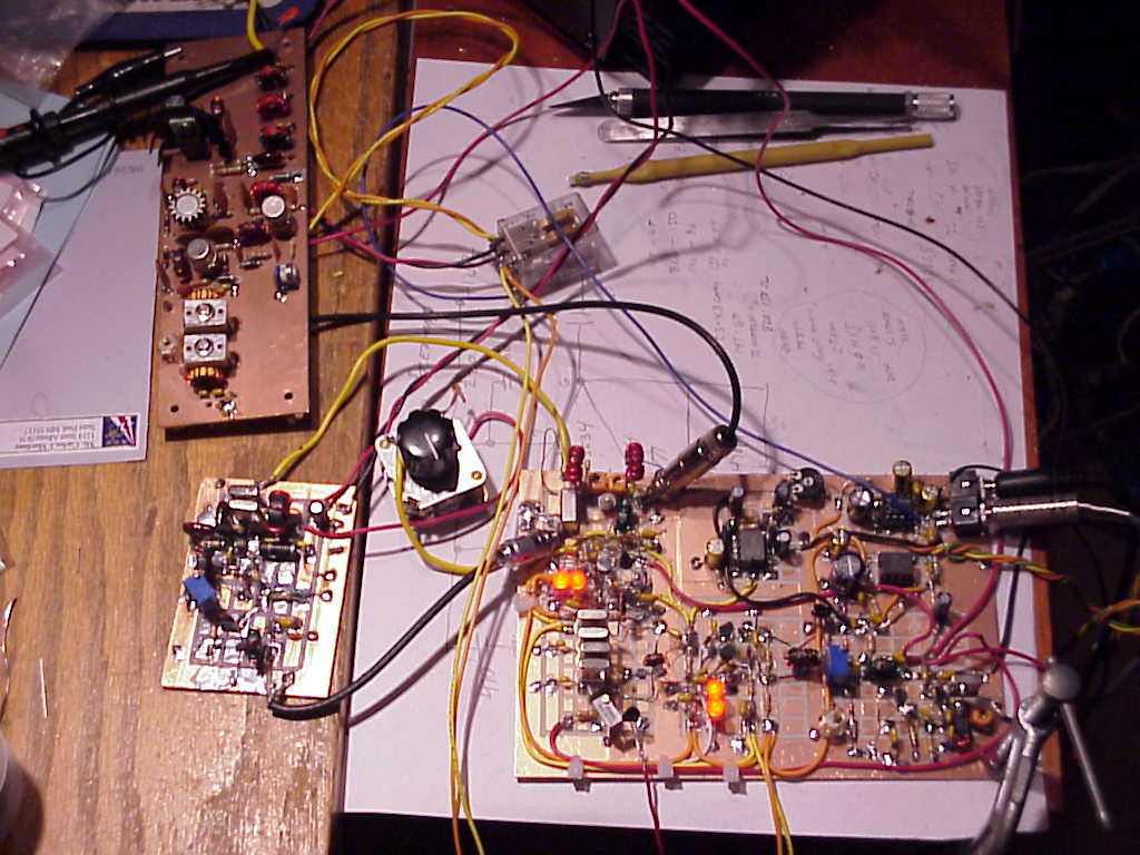
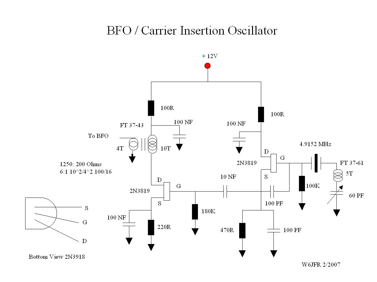
The Balance Modulator is also the Product Detector. While this would have been a great application for another TUF-1, I used a conventional diode ring with resistive and capacitive balance.The parts count are a few more but the cost is way less and the carrier balance is really optimized. The carrier insertion oscillator BFO is a nothing more than a two stage 2N3819 FET oscillator. The carrier oscillator is set on frequency using an inductor (5T on a FT-37-61) and a 60PF trimmer in series with the crystal. This is similar to the VXO approach.
Some Board Close up Shots of the Filter
Second Generation of the Mainboard and VXO
Switched Xtal VXO Modification
Balanced Modulator Product Detector
BFO Carrier Insertion Oscillator
Update 4/13/07
I purchased two custom crystals, 11.5335 MHz, so that with the doubler VXO would extend the frequency range to the upper portion of the 17M band. These were installed in a second VXO and tested. The range is 18.149 to 18.168 MHz and thus the possibility of a switched VXO will give almost full 17M coverage. The bad news is that two crystals cost nearly $50 which is literally more than the cost of parts for the whole radio. I made the investment so I could try to cover the hfpack frequency of 18.1575 MHz USB. On Saturday I hope to make some contacts on the net frequency. I also have purchased crystals (6.144 MHz) so that with the 11.520 MHz VXO working straight through should cover the 4th channel of 60M. Stay tuned.
Update 5/15/2007
The 17M V.2 transceiver was modified to include a switched VXO so that a greater frequency spread would result. It was a puzzling situation to come up with a method of switching the two crystal frequencies. I finally came up with a plan to use a small dip relay that was controlled by a panel mounted switch. Thus the crystals could be loacted very near the 2N3904 oscillator. The transceiver is now V.3. There are two frequency ranges; 1) from 18.122 MHz to 18.144MHz. and 2) from 18.150 MHz to 18.168 MHz.
DX Contacts on the 17M HB Transceiver GD6IA, Alex, on 2/24/07 at 1722 UTC 18.125 MHz. My report was 5X7. I was driving the HB SS Linear to 100 Watts out and the antenna was an Extended Lazy H at 50 Ft in the Pine Trees. GD6 is located at PEEL on the Isle of Man. DX contacts can be made using a Home Brew Radio! The version used was the V.2. (See www.gd6ia.com for more on Alex's station.) |
|---|
23.04 Mhz VXO
Experimental 23.04 MHz VXO using standard Computer Crystals.
11.520 Mhz VXO is doubled to 23.04 Mhz. The LO signal is above the filter center frequency. The doubler consists of two diodes and a post doubler amp using a 2N3904 to bring the signal up to 7 dbm to drive the TUF-1 Mixer. A pot in the output of the emitter adjusts the drive level to the proper value for injection into the TUF-1 mixer.
The VXO is a first for me and this is where you end up asking why I didn't try this before. The Computer Crystals are cheap and offer a source of stable RF for the local oscillator. It is not like a VFO as there is a practical limitation on how much you can swing the crystal but in this case the 11.52 MHz crystals are used in what is called a Super VXO and with a diode doubler provide a 30 khz coverage. On 17 Meters that is 1/2 the phone band. The circuit constants play a large role in maximizing the frequency spread. The basis for the VXO is that the inherent motional capacitance of the crystal is electronically tuned to expand the frequency range of the crystal. Generally lower frequency crystals have less of a spread.That is why a low IF and a high LO tends to maximize the frequency spread. Also the tuning is non-linear. At the lower (less) capacitance settings the frequencies are closer.
The final version uses three crystals all 11.520 MHz. This is probably a Super Super VXO. Thanks to Jim Kortge K8IQY who suggested the frequency doubler approach.
In looking at the 4.9152 IF frequency it occurred to me that if you provided an LO signal at 2.2 Mhz, 40 Meters would result. I built a 2.2 MHz VFO and a suitable bandpass filter and SURPRISE! 40 Meter signals were a perfect Q5. Because the 17M VXO is set above the IF frequency and to obtain USB the BFO must be in LSB since there is a sideband inversion resulting from the frequency subtraction. By adding 2.2 Mhz to the IF frequency the sidebands are not reversed and so the resulting 40M signals are automatically on LSB. What a bonus!. The VFO has been set for a small range, about 120 Khz, resulting in coverage from 7.165 to 7.285 Mhz. The VFO uses a large air core inductor wound on a ceramic form and a 50 PF variable provides a linear scale. The total capacitance is around 300 PF. This is a very stable VFO. It is a classic Colpitts circuit. The VFO is built in a small extruded steel box and the Variable capacitor is connected to the VFO via a short length of RF 174/U coax thorough an RCA connector. This allows mounting the VFO tuning capacitor remote from the VFO itself. I have built a 40M power amp and have run some tests. The power out is about 6 to 7 watts and uses a 2SC2075 as a final transistor. This is far less expensive than the 2SC3133. I was so impressed that I started construction of second unit that will be dedicated to 40 meters. Cosmetically I hope it will look better than this first prototype. When I get that completed I will post photos.
The first contact with this version was made on 2/6/07 with a station in Michigan which is about 2000 miles from my QTH. That is a difficult contact at 100 watts let alone about 7 watts. There is much to be said for QRP! More with less Rules!
Forty Meter Update. (2/20/07)
I noted that the output at the higher end of 40 Meters looked a bit strange on the scope. I hadn't noticed it before as most of the time I hang around 7180 to 7220. I think it may be a case of frequency mixing or harmonics and the filters not being able to do their job. The third harmonic of the VFO is in the 40 meter band. I did add a filter after the VFO and that helped but did not completely eliminate the problem. So I am going to attempt a different remedy. I found that one of the stock crystal frequencies is 12.096 MHz. If you mix that with the 4.9152 the result is 7.180 +/-. So I ordered some crystals and will see if that solves the problem. That should give me around 20 Khz around 7.180 and hopefully assure a clean output. I have now moved the original prototype to 40 Meters and the second unit is on 17Meters. I will report the results when I get the crystals.
Forty Meter Update. (2/24/07)
The 12.096 Mhz Crystals arrived and I installed them in a VXO circuit to test using the LO frequency above the band and hopefully tune the BFO to USB since with the LO above the IF mixing scheme there is a sideband inversion. Well the VXO gave about a 12 Khz spread and I was able to move the BFO to USB but not fully as the resulting signal was not of good quality both on transmit and receive. I suspect that if a higher IF were used then a larger spread would result. Thus it worked but not fully desirable. Back to the VFO approach. In observing the output I note that on the lower end of the band (7150 to 7200) that this mysterious signal does not appear in the output. It is only when you go from 7200 to 7300 that there is output showing up in direct proportion to the frequency. So something in the bandpass filter design must be amiss to allow frequencies to slip through. Other thoughts inlude a higher order bandpass flter design or a band reject filter just before the RF amp board.
I built a band reject filter using software available free on the Almost All Digital Electronics (AADE) website. This three element Cheyshev band reject filter follows the Double Balanced Mixer and ahead of 7.0 Mhz bandpass filter and is interspersed bewteen the RF amp board and the TUF-1. The filter has a 400 Khz bandwidth. The rejection is on the order of 30 DB. The concern was that the third harmonic of the IF Minus the VFO was being amplified. After the flter was installed I hooked my O scope up on the output of the RF amp board and keyed the microphone. The strange looking output has now disappeared. The band reject filter was easy to construct using standard capacitor values. I will post a drawing of the filter.
This experimentation today suggests that some of my approaches to using filter in a USB mode may not pan out too well. So I have some more experiements to run. One is of course to reapeat the tests using a higher IF such as 7.3728 Mhz. I have successfully used USB with 8.0, 9.0 and 10.0 MHz ladder filters in a VFO additive mode. I suspect a problem was the 4.9152 BFO crystal could not be adjusted enough.
March 4, 2007 Update
I built the AGC circuit and installed the board on the 40 Meter transceiver. The foreign broadcasts require the use of an AGC circuit otherwise it is ear splitting to tune across their carriers. I did determine that the FET switch on the transceiver board needs to be a true FET Analog Switch such as the 2N4856. I had been using a 2N3819 but found superior results with the current device. It now also has an S meter and that makes for a nice addition. I did some work on the VFO to imporve drift and long term stability and also managed to build a 40 meter Filter for the Solid State Linear Amp. On Forty Meters the amp will do 200 watts out. I did increase the bias on the final transistors and added a cooling fan. The amp runs cool and is a welcome addition on 40 meters. Quite a few contacts have been made on 40 all across the US and I am pleased with the results. I now am at a stage of having to pakage this unit and I think I have hit upon an idea for a retro vintage look. Photos will be posted when I have completed the packaging. I was very impressed with the receiever during the contest this weekend. For a single conversion without all of the bells and whistles it did very well.
March 9, 2007
I have been doing some experiments with the AGC and S meter circuits. While I did get an antique 500 micro-amp meter to do its wild wiggle the meter was just too physically large and that is when I hit upon the idea of an LED for an S Meter and that seems to work just fine. The LED simply replaces the meter in the AGC circuit. I set full brilliance to what I would think is an S9. Most of the times that is used as a standard. If you light the lamp fully then you are an S9 or better signal. The Classic "You aren't even wiggling the S-Meter, but Q5" is the almost dim LED. Works for me.
March 18, 2007
The 40 Meter radio is now in a Homebrew Case. See the photos below. I had a problem for two days with the radio working on transmit but no receive. It turned out to be the wire going from the output to the volume control pot and then to the LM386. The wire was pinched by a bolt holding down the VFO Tuning Cap. It was shorted to ground but since it was in a cable bundle it wasn't clearly visible. Sometimes (many times) the not so obvious is the problem!
20 Meters
March 1, 2007
I just discovered that All Electronics in Califiornia is selling 9.8304 MHz computer crystals at 5 for $1. If one were to use a 12.0 MHz VXO with a diode doubler (producing a signal at 24.0 MHz) and mixing that with a 9.8304 MHz IF that would result in a 14.170 MHz USB signal. So the next effort will be to build a third unit for 20 meters. Stay tuned for the results of this build. Some refinements have been made to the two prior builds that improve performance. The Rx RF amp has been biased "hotter" so that the receiver sensitivity has been improved. The same goes for the biasing on the first Tx transistor following the BPF. Overall the output has been raised slightly and that means more watts to the antenna. The final transistor has been changed to a 2SC2075 which is rated for 4 watts AM and 16 watts PEP available from RF Parts Inc. for under $2.50 in small quantities.
March 4, 2007
I have the VXO working and that swings from 14.175 MHz to 14.200 Mhz. That is ideal for me as that ends up being the portion of the band that I usually will monitor. Plenty of DX is heard.
March 8, 2007
The batch of 9.8304 Mhz Crystals arrived and now I have to match the crystals. With the 5 units for $1 deal from All Electronics I purchased a large quantity (good) but matching that large group is a time consuming job (bad).
The first prototype was built on a 4"x6" piece of single sided copper board. My son has been dabbling with 3 axis NC milling machines and one of his first attempts was to take a small 3 axis manual mill and convert it to NC. He did that but was unhappy with the results so he scratch designed several three axis NC machines. Thus he abandoned the manual machine and I inherited the machine. (Seems only right since I funded the original manual machine.). Bottom line every ham needs one of these. They are available at Harbor Freight. There are two low cost models. One goes for about $300 and that would be perfect for circuit boards the next up cost $500. That is the one I have. I took the 4"x6" board and milled out small areas on the board and created islands consisting of small squares. This provided many connect points and the areas around the islands formed one continuous ground plane. So a common ground is an easy matter. The mill can also be used to drill circuit boards. You will need a good vise that mounts to the bed of the mill. My son (a Mechanical Engineer) took the vise and created slots in the jaws so that a standard circuit board fits in the slots. He also made me some tooling to provide support under the board when it is being milled.
The first board while not a beauty worked very well and is solid! The second board will use commercial single sided copper Vector board with holes on 0.1 inch spacing. I did use the mill to cut a 4"x5" piece out of the 4.5"X17" standard Vector stock. The concept of the second board is that the top is a ground plane and all connections other than ground are made underneath the board. Ground connections are soldered directly to the top of the board. The objective of the second board is smaller size and to include the agc circuitry on the board as well. It will look a little more sanitary. There is probably Zero performance difference in the two boards but the first does enable more experimentation.
The second approach is for when the design is optimized and stable. This two step approach also permits a better flow from each stage and reduction of cross overs and more direct connections. This all goes to make a big difference in something that "sorta works" or "almost works" and something that works consistently. With the copper clad perfboard when a component will be connected on the underside a 5/32 drill bit is used to slightly ream the top part of the hole so that as a component passes through the hole it will not short to ground. Those components that go to ground are simply soldered to the top part of the board
The key to success in building projects similar to this transceiver is to have some decent test equipment. An O'scope, DVM, Signal Generator, Frequency Counter round out the list. Many good bargains can be found on the internet and one does not have to spend thousands to acquire some first rate test gear. My O'scope is a 60Mhz Tektronix that I got for $100, the Frequency Counter is an HP 80 MHz unit that I paid $48 and the Signal Generator a Heathkit that I paid $35. The DVM is a B&K and I paid $45. So for a little over $200 I got some decent test gear. There are many pieces you can build yourself so don't overlook that as a possibility. A 30 Mhz O'scope can do much of the work needed for the HF Bands. Be careful what you are buying as there is a lot of junk out there. Much info is available on what is good or not good. A Sweep type oscillator can be made out of crystals and a VXO circuit. This is useful for aligning filters. Wes Hayward's book Solid State Design has a whole section on homebrew test equipment that is just as good as costly commercial equipment. Attenuators and a decent well regulated power supply are other items. Don't overlook the soldering iron. A grounded type temperature regulated is a must. Forget about that 100 Watt $20 Radio Shack soldering iron for working on Surface Mount devices! Get an iron that has accommodations for various tips.
Electrical connections to a power supply are always as hassle. I also found that connecting directly to my Astron with a short length of wire (12 inches) was picking up hum from the supply. I came up with a power panel distribution tool and it is shown below. The breakout panel is connceted to the Astron through a 4 foot length of power cable. I now have more conection points and no hum.